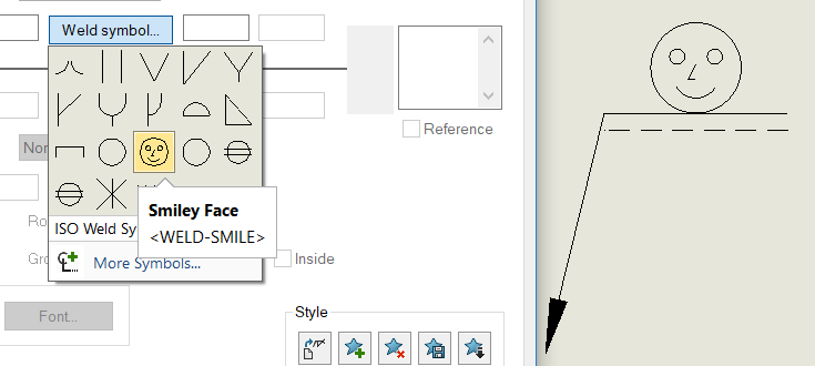
When creating welding diagrams and defining the types of welds you want to place on your parts, there is a list of standard weld types that can be used. If your company has created its own weld symbols or wants to use non-standard symbols, you can make them yourself for use in SOLIDWORKS.
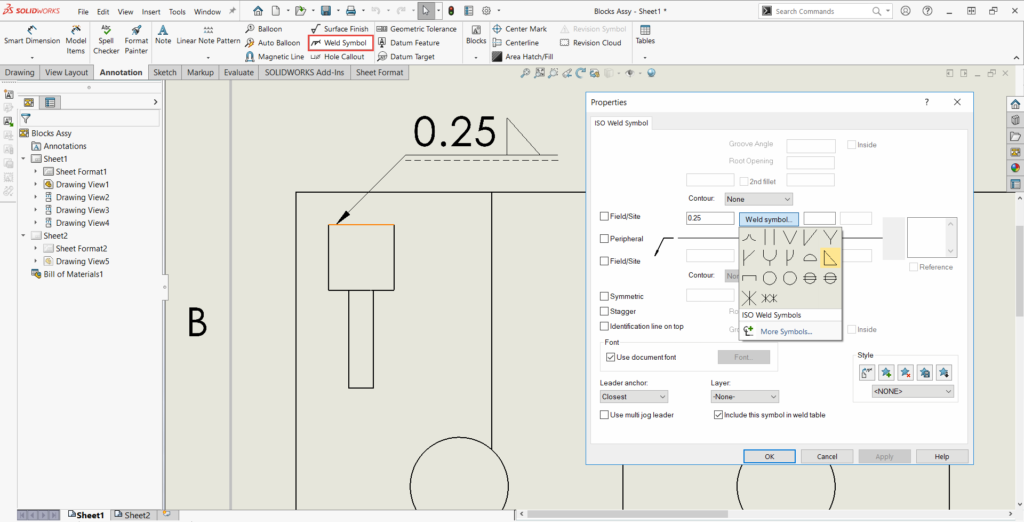
To create a custom weld symbol, select the Weld Symbol option on the Annotations tab to add a weld symbol to your drawing. You can customize the settings you want to use for your weldment specification.

If the symbol you want is not listed here, it can be manually added by editing your symbol library file. To find the location of your symbol library file, navigate to Tools > Options > System Options > File Locations > Symbol Library File. Navigating to this folder location will display the symbol library file called gtol.sym. This file is version specific, so any edits to this file will need to be made to the same file for other versions you may have installed on your machine.
Right-clicking on this file will allow you to select Open with and select the notepad program or any other text editor you may have installed on your machine. I recommend searching for the weld symbol section that interests you. Many standards are available to edit in this section, so be sure to add your new symbol to the correct standard.
Custom Weld Symbols Structure
At this point, you will see all the symbol options listed that start with an asterisk (*). The structure of the coding is as follows:
*[Shorthand Code],[Full Name]
A,[Entity Type] [Dimension Inputs]
- The shorthand code is the internal code used by the software when linking values. This can be any custom code that is normally 3-5 characters long. Make sure that this code is unique to the standard you are in.
- The full name would be the full name of the custom symbol that you are creating.
- The entity type will be either ARC, CIRCLE, or LINE, depending on the geometry that you want to make, as these are the only types of geometry that SOLIDWORKS can use in symbols.
- The dimension inputs are structured in X and Y coordinates and are used to determine the geometry. Note that integers must have a decimal after them, and there are no zeros before the decimal for numbers <1 in this syntax.
As shown in the above image, a normal fillet weld has its code listed below as an example. These three-line elements that are used will create the triangle that is the fillet weld symbol.
*FILL, Fillet
A,LINE .1,0.,.9,0.
A,LINE .1,0.,.1,.9
A,LINE .1,.9,.9,0.
The syntax for each entity type is listed below:
Line
Xstart, Ystart, Xend, Yend
Arc
Xcenter, Ycenter, Diameter, Degreestart, Degreeend
Circle
Xcenter, Ycenter, Radius

Once you have finished creating or modifying the weld symbols, you can save this file and restart SOLIDWORKS for the new symbols to take effect. You can then distribute the new symbol library file to any others at your company that will need the new weld symbols to be shown. After performing upgrades, you can open this library file and copy over the custom elements that you have added.
More SOLIDWORKS Resources
If you’re interested in learning more, check out these additional resources below:
- SOLIDWORKS How-To: Copy a Part Using Virtual Component
- SOLIDWORKS How-To: Normal To Orientation Trick
- SOLIDWORKS How-To: Create Virtual Sharps in Sketches
- SOLIDWORKS How-To: Add Relations with Shared Sketch Endpoints
- SOLIDWORKS How-To: Change a Component Color in a Drawing View
Contact Us
You’re passionate about your business. We’re passionate about fueling your success. Reach out today, and let’s start a conversation.
Get in touch with one of our experts: 800-454-2233
Share
Meet the Author

