Think like a structural engineer.
Yep, that’s right, we’re borrowing thoughts from the civil engineering field. In buildings, bridges, dams, and many other civil engineering structures, reinforced concrete is a composite material, and how it is analyzed and designed can teach us a lot about how to design 3D printed composites. Of course, like concrete, these methods are estimations, and rigorous study of factors of safety is needed, but by applying these principles and testing, the industry and its usage of these tools can be pushed forward.
There are numerous items that can be discussed when designing 3D Printed Composite parts. They can be designed for:
- Bending
- Shear
- Torsion
- Compression
- Buckling
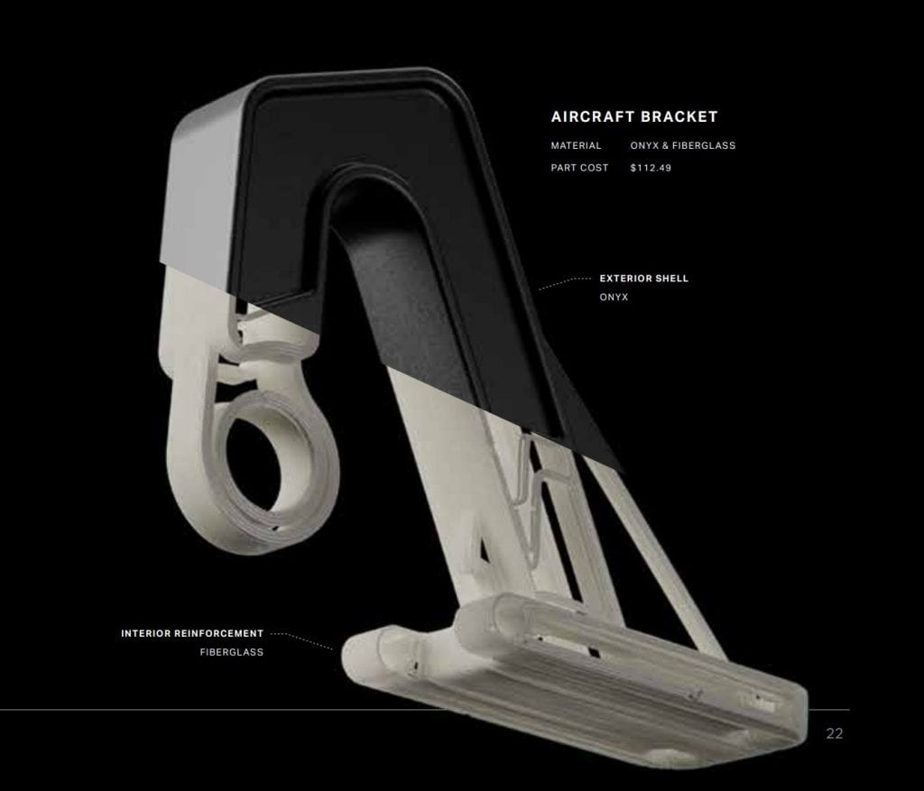
This is part 1 in a series of articles in which we start with designing a structural member that resists in tension as it is the simplest. However, some brief ideas need to be clarified for anyone unfamiliar. In a composite, there is a base material of plastic. The Onyx material is the default for Markforged 3D Printers, so that is what will be used here. Then, there is fiber that is inserted in the base material to reinforce its tensile strength. This is carbon fiber, or Kevlar, or other Markforged materials. The image below shows what this is like. It shows a cut away of the base plastic matrix from the reinforcing fiber.
Now that we understand what a composite part is, let’s get to analyzing a simple part that has a square cross-section, carries a load in tension, and has the reinforcing fiber running vertically throughout in the direction of the loading. This could be for hanging a piece of equipment, and the design check is to make sure this won’t fail, fall from the ceiling and destroy that piece of equipment. Below is a model of the part that will be analyzed in example cases.
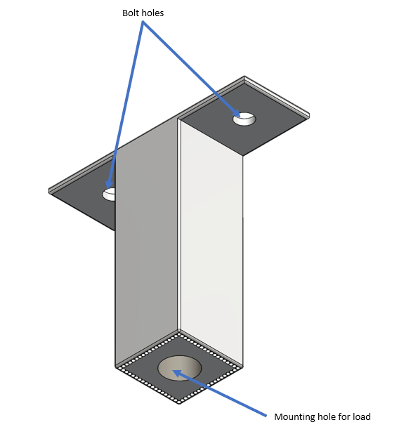
This part gets bolted to the ceiling through holes in the flange and then bolted to the part it holds below. Assume, for now, that the flange that the bolt goes through has adequate strength, as does the mounting hole on the bottom. The first thing to note is the possible failure modes. You have a tensile failure mode, where we assume everything snaps at once. There is also a delamination failure mode, where the interface of the base material and reinforcing fiber breaks apart and as a result, no longer carries the load as a composite, significantly reducing the strength. We’ll look at each of these cases separately.
Tensile Failure Mode Analysis
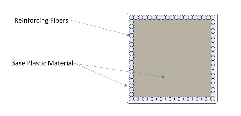
By looking at the cross-section of the previous image, we can see that we have two different materials, each contributing to the strength of the member in tension. An equation for the combined strength capacity would be:

One thing to note about this equation, once failure of one of the materials happens, it no longer holds true. As a result, we have to assume the composite behavior is only valid up until the yield strain, or failure strain of whichever material has the lowest value. In this case, it’s going to be the reinforcing fiber. Using the carbon fiber material Markforged provides, it fails at a strain of 1.5%, while the plastic matrix, in this case the Onyx material, fails at a strain of 58%. As a result, the plastic matrix won’t get near yield strength, so yield strength or ultimate strength of base material should not be used in this calculation. Instead, the stress of the plastic at the failure strain of the reinforcement needs to be used.
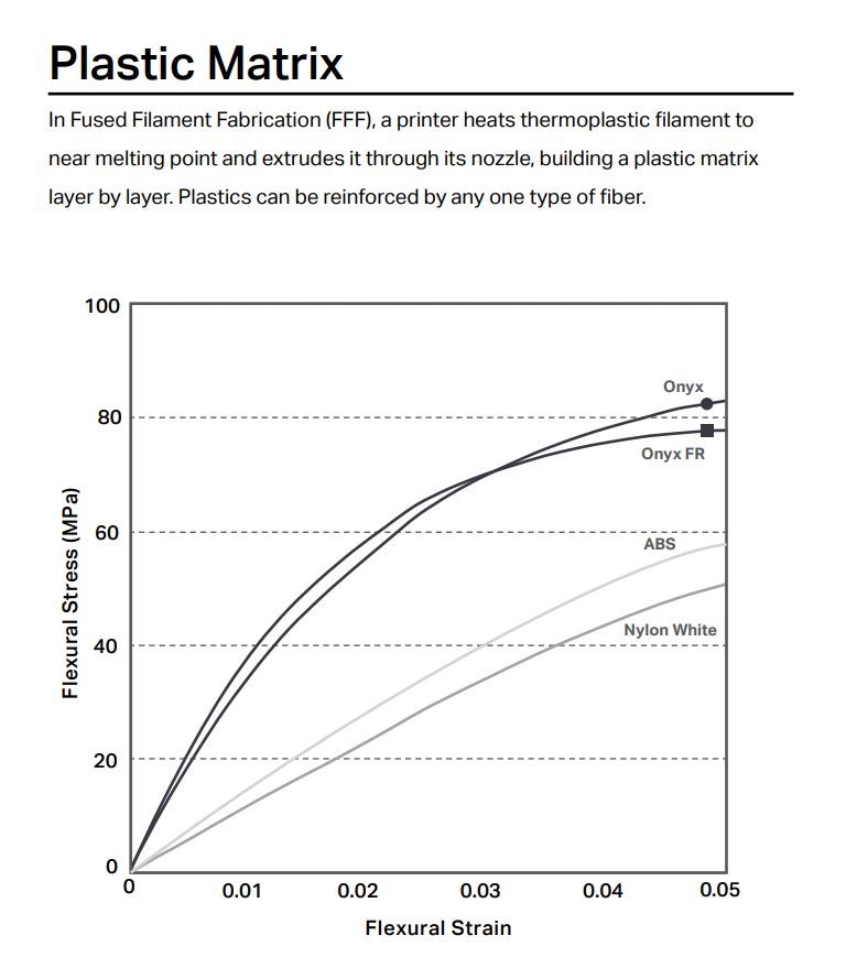
There are a couple of ways to do this, as reinforcements change, using a stress-strain chart like the one to the right to look up the stress at the given failure strain and use that value for calculation. Or as I’ve drawn by blue line, coming up with a more linear representation of the stress between unloaded and the yield stress of the plastic matrix. This is a conservative approach, as the allowable stresses predicted by this line are lower; however, this has the added benefit of being easy to program logic into a spreadsheet by using simple division of the failure strain of the reinforcement divided by yield strain of the plastic matrix and multiplying it by the yield stress of the plastic matrix will give you the stress at any point on this line that you need. It also accounts for an additional “factor of safety” as it is below the stress-strain curve of the material, underestimating its strength.
It’s important to discuss the assumptions that have been made so far. In the example analysis, it is assumed that there is a solid chunk of material, when in fact it could be porous inside. It’s also assumed that the fibers are running along the length in the direction of the tension applied and that there is bonding that has happened between those and the reinforcement.
After analyzing for tensile strength, it’s important to make sure delamination, the separation of the bond between the base material and the reinforcing fiber doesn’t happen. If it does, then the part loses its strength.
Delamination
The strength of the part as calculated above is only true under the assumptions that the base plastic material and the reinforcing fiber stay bonded and that the strain in both is the same, no slippage between them.
If one material slides relative to another this is referred to as a delamination failure. It’s a complex mode of failure, and a reason that proper factors of safety should be used on any part.
Delamination inside of Markforged composite parts isn’t currently well understood, as a result, printed parts are usually tested for strength rather than analyzed in a deterministic manner, but I’ve been developing these ideas of analysis.
One possible way of calculating delamination failure is to calculate the shear from the load at the interface of the two materials, then assume a shear strength of the bond between them. At a maximum, the bond strength is going to be that of the weakest material, since if the bond was stronger than the weakest material, the failure would happen in the material. At worst, it’s significantly weaker than the base material.
Here are some of the variables that are present in this and it can be difficult to account for them all:
- Orientation of fiber
- Materials of both base plastic and reinforcing fiber
- Bond strength of the materials to each other
- Friction between the two materials
- The interaction of the materials, tension for example “squeezing” the reinforcing fiber
- Thermal effects in certain operating environments
- Tolerances of the fiber
- Cross-section of fiber
- Spacing of reinforcing fibers
While we can’t account for all of these, we’ll discuss a method that estimates the resistance against delamination to the best of our ability. Here are the determinations that need to be made in order to estimate the strength before delamination failure happens:
- Interface area of base material and reinforcing fiber
- Interface bond strength between the base material and reinforcing fiber
Calculating the Interface Area
There are many assumptions that could be made here. First off, the reinforcing fiber is a circular cross-section therefore the interface area is the length of the fiber times the circumference.
This equation looks something like this:

This says the area of the bond = or equals, the circumference of the fiber times the length of the fiber. If several runs of fiber are used, then the lengths should be added together. This assumes that all of the fiber’s circumference is in contact with the base material. If not, modify as necessary.
Calculating Bond Strength
Bond strength is as already mentioned is an area where much is unknown and still requires more study, however, here is how I see a possibility in estimating its strength:
- The base material is weaker so we will use its material properties for this calculation.
- We won’t assume the full-strength of the base material, we’ll use a reduction factor on it.
- We’ll use the stress value of the material at the failure strain as determined in our previous analysis, the lesser failure strains of the materials.

The above equation says that the stress the bond can handle is equal to the stress of the base material at the failure strain multiplied by a strength reduction factor. If onyx is being used, the stress at the 1.5% strain, where the carbon fiber fails is about 50 MPa. As for the strength reduction factor, what value should be used?
This area requires more study, as a result, I would start with something low, like 0.05 and only use it on non-failure applications. If a physical test is performed to failure, data can be used to calculate something more reasonable, and build confidence in future predictive analyses.
An Example Calculation of Delamination Failure
Let’s look at an example and how this would be calculated.
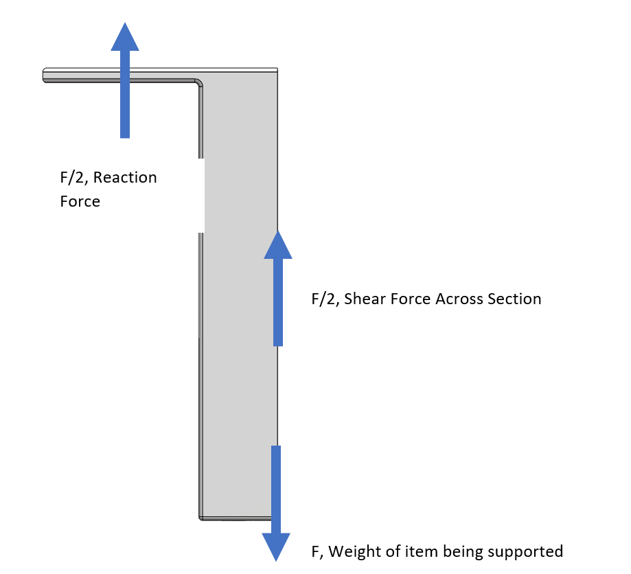
Returning to our example from the tension analysis, the shear in the direction of the load will be the largest. And the maximum shear will need to be ½ of the load based on the shear diagram. Let’s use the variable F to represent the load being carried, below I’ve added the free-body diagram and it can be seen that at the interface, the shear that needs to be carried through it is F/2. This leads to the following equation:
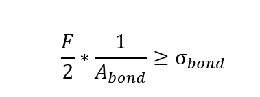
If that statement is true, then the part will delaminate and fail prior to the full load capacity being reached.
This creates an idea that may be counterintuitive. In general, for tensile carrying parts, longer sections for the same load will provide better resistance against delamination since they provide a larger interface (the circumference stays the same, but the length increases) area between the two materials to distribute the shear force to. The problem here can be that for the same strain, a part that is twice as long will displace twice as much, so if the part design has displacement criteria on it, then this will make it harder to make it longer.
At this point, I’ve covered the design and analysis of tensile members with what is known at the moment. To design these structural members for 3D printed composite technology, it is simply necessary to think of a few of these factors. In future parts of the series, I will cover analysis for flexure, torsion, and may even expand on a few items I’ve covered here.
This is not exhaustive. It is based on the study of mechanics and stress analysis and is still part art. If you run any testing and would like to share information with me, I would be happy to convert any data you have into better guidelines for design in this series. For now, I’m sharing how I would design components that are being printed out of 3D Composite Parts. In the future, I’d like to design some parts, run some tests and make the guidelines more thorough.
Want More?
If you are interested in learning more, check out these resources below:
Contact Us
Have a question? We’re always available to talk over the phone at 800-454-2233, leave a message, or for you to submit a request – just contact us.
Share
Meet the Author

