I have often been asked how to export using a custom coordinate System in SOLIDWORKS when it comes to CAM vs.CAD. In a nutshell, CAD systems like SOLIDWORKS and CAM systems use different directions for defining coordinate systems, specifically in regards to Y and Z. The result is, when a model is exported from SOLIDWORKS and imported to a CAM system, the model comes up in the CAM system in the “wrong” orientation. The good news is a SOLIDWORKS user can make their own coordinate system specifically for use in the export process, thus resulting in a model coming up in the correct orientation in the CAM program.
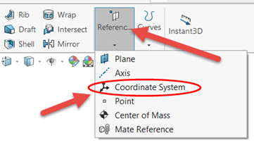
The first step is to make your new coordinate system. Click on the “Reference Geometry” button on the Features tab of the Command Manager:
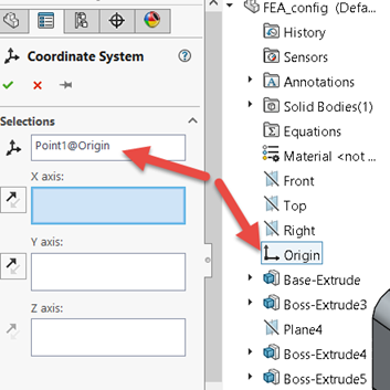
Next, select a point on the model or use the Origin of the model to define the origin of the new coordinate system:
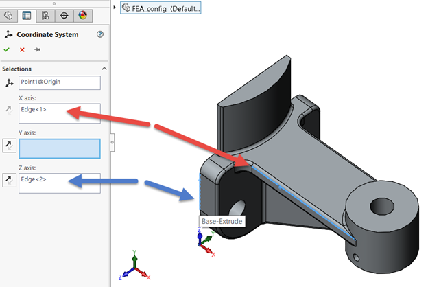
Now select edges to define any two of the X, Y, and Z axes for your coordinate system. Use the double-arrow buttons if you need to reverse positive direction. In my case, I’m picking edges on the model to define X and Z as shown:
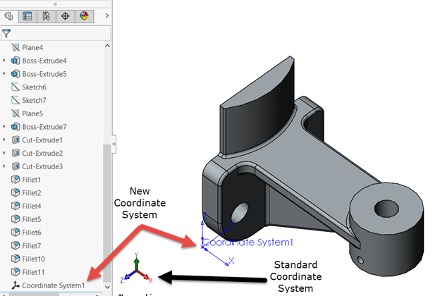
The final result is a new coordinate system. Notice the direction of X, Y, and Z in the new coordinate system vs. the standard coordinate system.
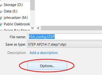
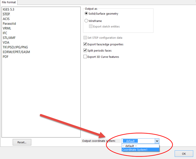
To export the model using the new coordinate system, do a Save As, choose your file type, click the Options button, and make sure you change the coordinate system from “Default” to your new coordinate system near the bottom of the dialog box.
And, that’s it! Now you can save out any SOLIDWORKS file to any coordinate system you can define.
Share
Meet the Author

