We’re in Part 2 of our SOLIDWORKS Flow Simulation series! So far we’ve covered the basics and the stages. Now, we’re going to take a closer look at a basic mesh.
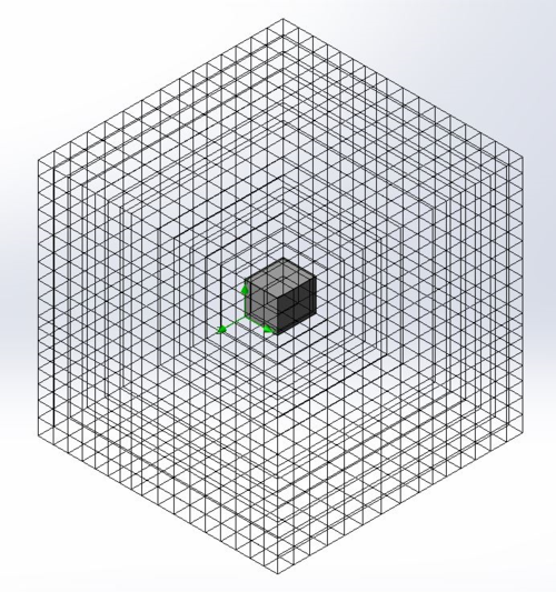
Above is an example of a basic mesh. It is the first stage of a CFD problem. It only sets its size based on the computational domain and ignores the model shape. To set this up, there are multiple settings related to it. Let’s look at the automatic settings screen first.
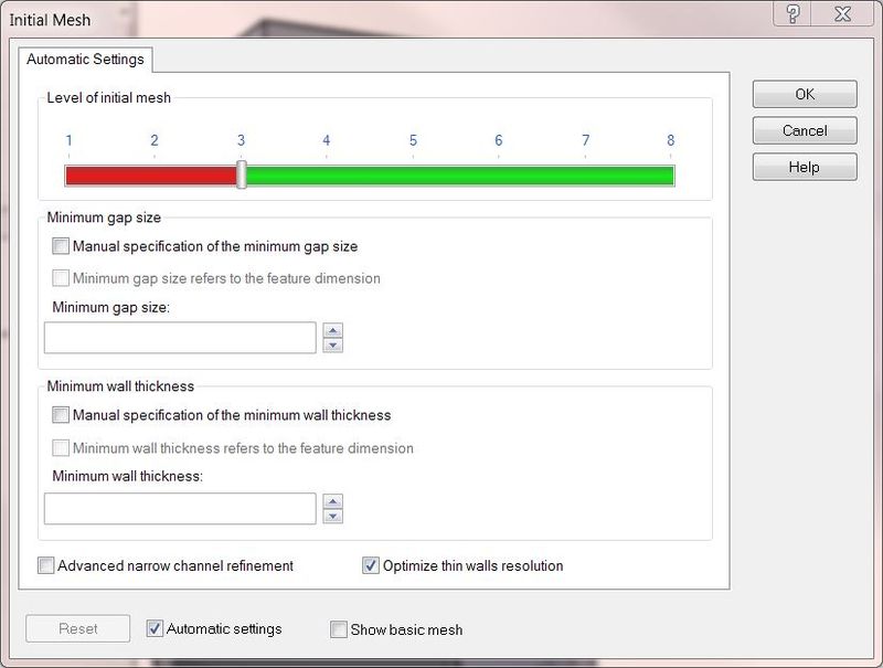
Only one item on the above screen is related to the basic mesh setting and that is the level of initial mesh slider (the bar with the red and green). Sliding it to a lower setting makes the basic cells larger and sliding it to a higher setting make the cells smaller. All the other options on this screen are related to transforming the basic mesh into the initial mesh.
Clearing the “Automatic settings” checkbox at the bottom, this screen changes to the image below. At this screen, it is possible to more accurately control the size of the cells in the x-, y- and z- directions by setting how many of them span across those directions.
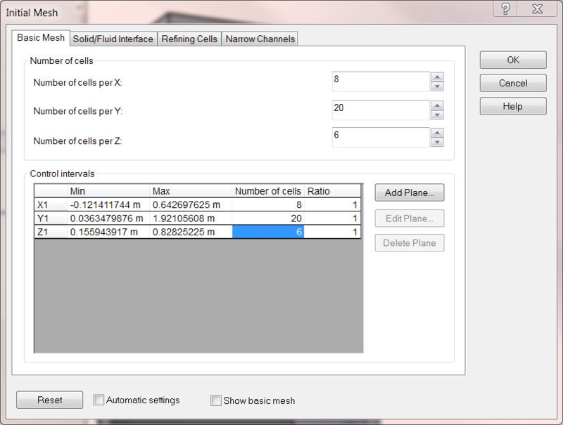
To control certain regions of the basic mesh, control planes can be used. Inserting control planes using the “Add Plane…” button seen in the image above allows control of different regions around the model to have varying size cells. There are many reasons why these control planes are useful. Some reasons are high-interest areas requiring more accuracy, time efficiency of analysis, and proper cell alignment with a particular face to minimize partial and/or irregular cells. The image below shows an example of control plane usage.
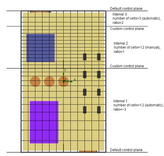
In the image above, setting values are shown to the right, such as the number of cells and the ratio of that control interval. The number of cells is easy to understand, but the ratio is not as clear. In this case, the ratio represents the distribution of cell sizes in a given interval. Since large elements right next to much smaller ones is bad, transition sizes are necessary. The ratio tells how large the largest cell is compared to the smallest. A ratio of two would mean the largest cell in that interval is twice as wide as the smallest. Negative ratios mean the cells shrink in the direction of the axis. A -3 ratio in the x-direction means that moving in the x-direction, the largest cell will be closest to the origin and the smallest cell, which is three times smaller than the largest one, will be further down the x-axis.
There is not much to the basic mesh other than these settings. Settings related to the model geometry are controlled to transform this from the basic mesh into the initial mesh of the problem. These settings are of most importance after this and generally govern the size of our problem more than the basic mesh. I’ll be talking about those in part 3 of this series so stay tuned in the future!
Next – Part 3: How to Use Meshing in SOLIDWORKS Flow Simulation
Lets take a closer look at an initial mesh. The initial mesh takes software defaults or user input settings related to model geometry and refines the basic mesh around the model geometry. Areas of curvature, thin walls, and narrow channels all play into how much the cells get refined.
Share
Meet the Author

