SOLIDWORKS Electrical Terminations Manager
Let’s continue where we left off in our Back to the Future blog and talk about…time travel! Another well known series that sees several time jumps is the Terminator franchise! In order to understand the sequels, you need to go back to the start and understand…how did we get here?
The robots have taken over! A silicon valley company responsible for developing self aware AI causes the downfall of civilization as the machines turned on their makers, and the last leaders of humanity are running out of hope against the robot army, resorting to last ditch strategic jumps through time on missions to snuff out the source of the problem to restore the future…whoa.
Well, in case you’ve looked around, AI, robots, and cobots ARE taking over, but in the more helpful manufacturing and industrial automation sense. And chances are you’re going to do some terminating of your very own on one of these revolutionary machines in the very near future.
Become a Terminator
In 2020, SOLIDWORKS Electrical now has a dedicated feature to help you become a Terminator. But before you take up your weapon of choice in hopes of saving future…project…timelines…let’s ask the question again, “How did we get here?”
Let’s go back to a darker time… the year is 2019. It’s a world where users scrap and fight for ways to define how a wire meets a component’s terminals. Wiring techs scavenge through drawings for any shred of helpful information. The engineer responsible for documenting termination information is left few options: USER DATA, gobbling up the part’s Mnemonic text (which may better be used to indicate pin signaling info), or direct text entry.
Jumping forward in time, the battle is won, a hope arises: a dedicated feature that let’s us define our possible termination options from a library, then define the termination style used wherever necessary with a simple drop down either at time of part creation or component entry into the project.
How to Use Terminations
So with the past behind us, let’s look forward to your next machine design…
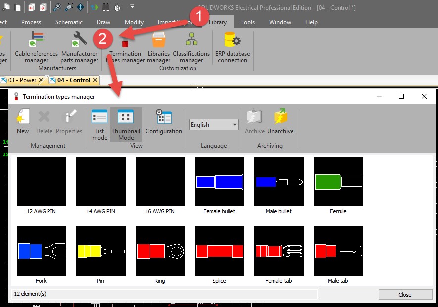
Terminations are defined in the library. To edit or add new termination types to the manager, we enter the library and visit the Terminations Manager section.
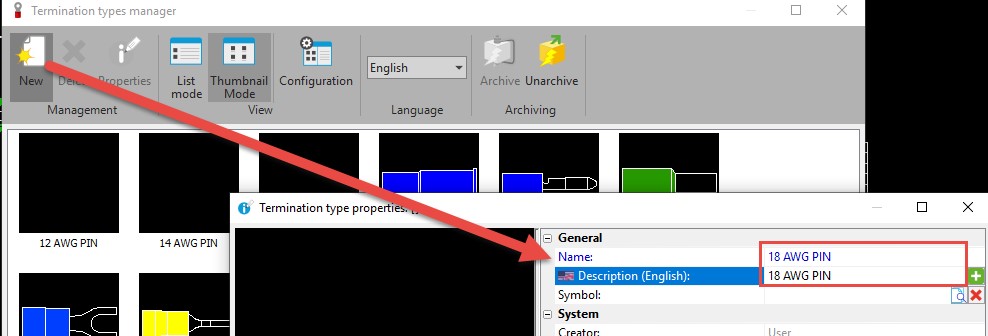
We have several stock options and here can easily add new options with a description and name, they are now available in terminations drop down; no symbol is necessary here unless you want it.
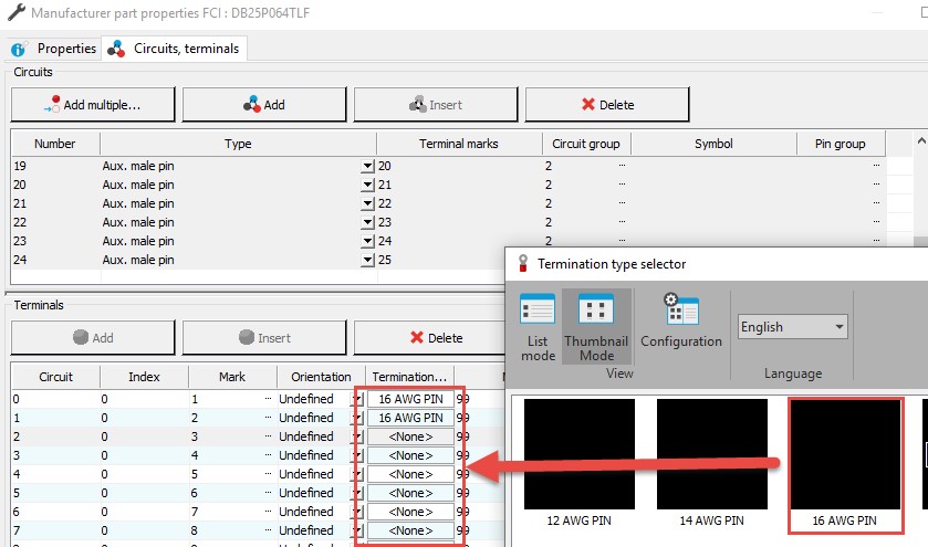
Once in your library, the terminations become available in 2 main areas. We can assign a default termination style on a manufacturer part’s terminals; now each time this part is chosen in a project, that termination is defined.
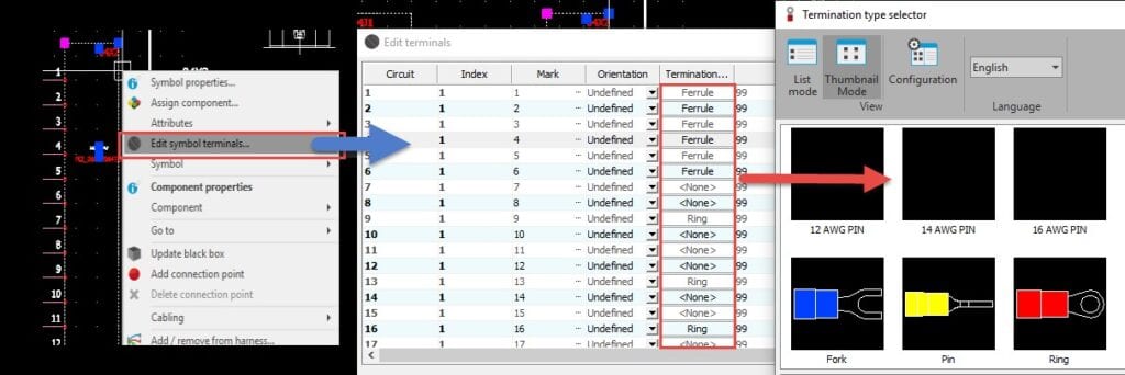
However, this designation, weather specified or left blank, can be modified on a component-by-component basis once in your project. In other words, we can set a part up to behave as it normally would, but are free to edit it on a case-by-case basis in your projects.
It’s as simple as editing the terminals on a component and choosing the termination possibilities from the termination selector.
Now that terminations are defined on the component on a per terminal basis, what can we do with them? Results can show up and be used in several areas starting with the wire or cable to from list, connection label attributes, and directly on schematics with the symbol terminal termination attribute readout.
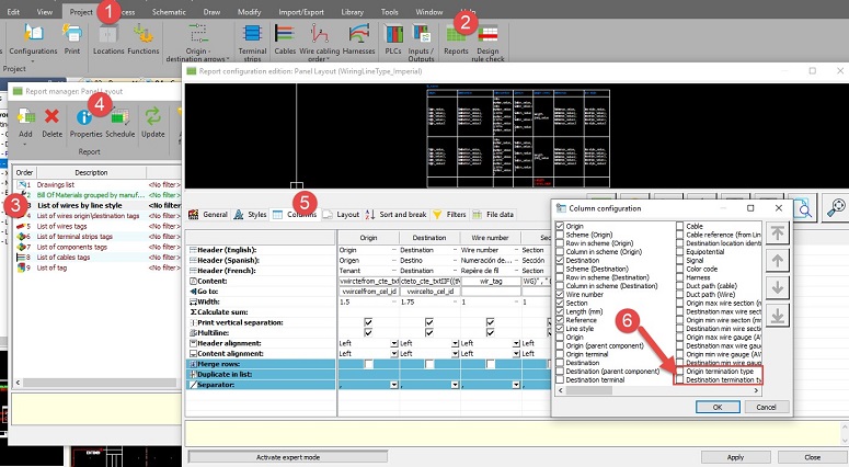
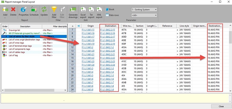
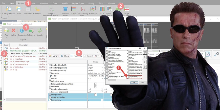
For the wire to from list, we simply include the termination information for the wire’s origin and destination and the readout will appear in the report preview, and be kept current with report updates.
The next 2 uses are applied in a similar way: first adding termination info to a schematic symbol, we can edit a symbol, and simply select the attribute related to the pin, and lay it at the preferred position.
Similarly, we can set the pin-by-pin termination attribute in a connection label, so our tables read out each pin’s termination information.
Clarifications: This doesn’t address the terminations from a Bill of Materials (BOM) perspective, only from a reporting and attribute perspective. If you need each termination as a separate part addition, then treat them as a traditional symbol / part combo. If you need terminations relative to a component on the BOM, add them to a component’s part list.
So take up your newest weapon and see how this nifty new dedicated time-saver can help you take down your next project’s terminator detailing with ease!
Contact Us
Did you like this tutorial? There’s more where this comes from. Find other blogs covering SOLIDWORKS Electrical by Evan or more on our YouTube Tech Tip videos.
Have a question? We’re always available to talk over the phone, for you to leave a message, or for you to submit a request – just contact us.
Share
Meet the Author

